Typical solutions of the past often featured a single knob with many potentiometers on the back – this maintains electrical isolation but typically while one lamp from one system is about to extinguish, one from another system is still too bright. A common variable voltage supply is used to provide a common dimming voltage which each system then grounds to activate the lamp. The problem here is that now that common signal must travel through each separate system, isolation has not been maintained and a fault current from one system can follow into and damage another system. The fault current and short circuit protection from the common supply may be too great for one of the systems grounding a lamp so short circuit protection needs very careful management to avoid fire risks which is rarely considered.
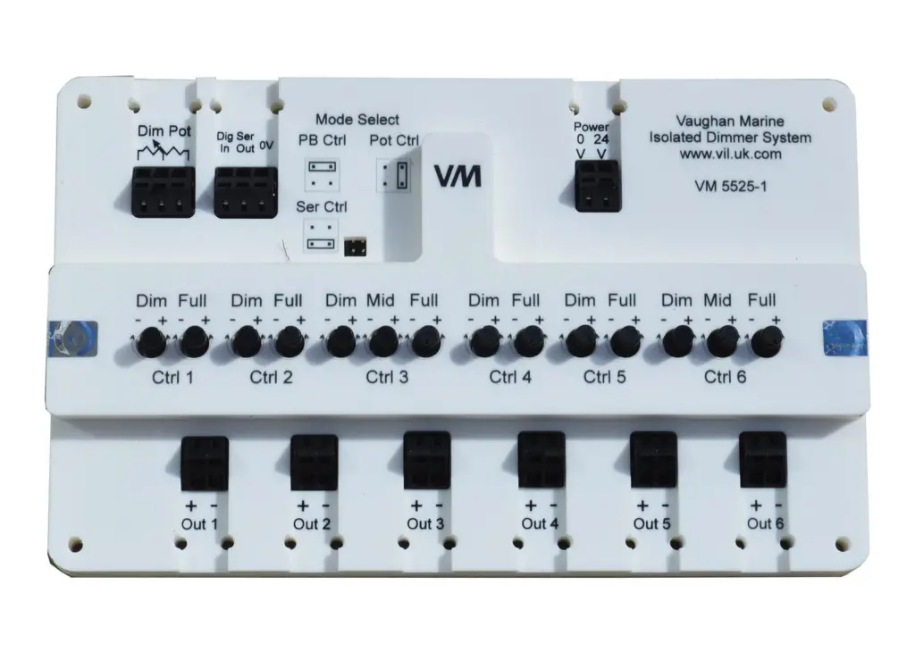
The cure, according to Wills Ridley, is to use the isolated dimming system. This starts with a six channel control card which can be controlled by a single potentiometer, or momentary push buttons. Each of the six output channels are fully optically isolated and can drive 1 amp 24V pulse width modulation (PWM) for lighting instrument systems. Its control system requires a battery backed up supply. If you need more than six channels then a second and more cards can be added alongside the first master card, all driven from that master card. Each channel uses PWM to control the circuits’ brightness, with calibration knobs provided to set the minimum brightness pulse width and the maximum brightness pulse width so different indicator lamps can be setup to reach minimum and maximum brightness together in unison with a linear extrapolated line between.
The output PWM frequency is approximately 100Hz, low enough so there is little likelihood of interference, but high enough not to suffer from flicker. The power supply is fully filtered as are the communications between adjacent cards which take place at a very low data rate also to avoid interference issues.
By Jake Frith