![MaritimeJournal[Seawork]](https://www.maritimejournal.com/wp-content/uploads/2026/09/MaritimeJournalSeawork.svg)

Linkspans refurbished at Woolwich
UK-headquartered specialist contractor AMCO has recently completed a refurbishment and upgrade of the four loading bridges, or linkspans for the Woolwich ferry in London, UK.
The Woolwich ferry is a vehicle and passenger service connecting the north and south circular roads across the River Thames. It is owned and financed by Transport for London (TfL) and is operated by Briggs Marine Contractors under a term contract.
In 2012, following detailed surveys, TfL concluded that the linkspans needed refurbishing and the hoisting mechanism required a major upgrade.
Speaking on behalf of TfL, Andy Thompson General Manager, London River Services said: “The linkspans were in need of refurbishment to handle the increased volume of traffic and improve the reliability for the ferry service for years to come.”
In order to achieve the required levels of service reliability, it was decided that the linkspan lifting equipment and the associated control systems needed to be replaced.
Andy continued: “We needed to ensure that we continue to meet the standards that we and our customers expect.”
In December 2013, AMCO was awarded the contract to refurbish the linkspans and replace the associated lifting systems.
BASIS OF DESIGN
Building on the initial specification AMCO undertook further detailed surveys and investigations to establish the operating parameters of the new systems. The aim was to develop a solution that would improve reliability of the service and reduce cycle times.
James Chappell, AMCO’s Contract Manager explained: “There were three areas that we needed to assess; the linkspans, the lifting equipment and the associated electrical and control systems. Each had their own challenges and in each case we were looking for the best solution that would provide the greatest life extension.”
LINKSPANS
The ferry terminals, on opposite sides of the river, each have two similar RoRo linkspans of 42.7m long by 6.5m wide by 5.0m high.
Each terminal consists of a piled, two-lane approach viaduct leading from the shore to two independent steel Warren truss linkspans. These lie side by side and parallel to the river. The moving ends are supported by reinforced concrete towers, which house the lifting equipment needed to adjust the elevation of the linkspans to match the height of the ferry’s vehicle deck over a tidal range of more than 7.5m.
The road decks of the linkspans are supported on bronze bearings. These allow the deck to twist in response to the rolling movement of the ferry from passing river traffic and the loading of heavy vehicles.
James Chappell continues: “One of the first jobs that we did was to carry out a detailed modelling exercise of how the linkspan performed structurally. This was important as it allowed us to assess whether the road deck complied with current Highways Agency loading requirements. It also meant that we could ensure that the walkway met the standards for crowd loading.”
Modelling the linkspan in this manner showed that only a minimal amount of strengthening was necessary. The model also identified that the road deck plate welds were being overstressed in the area of the wheel tracks over the linkspan.
The solution to the problem was to over-plate the road deck and replace the tarmac surface with a mastic asphalt system that would flex with the linkspan.
All elements of the work had to be undertaken such that the net weight of the linkspan was not increased. The reason for this was to ensure that the retained components of the lifting system were not compromised.
EXISTING LIFTING SYSTEMS
The existing lifting systems raised and lowered the linkspans by means of electrically powered winches and wire ropes. The replacement of these systems was necessary as much of the equipment had become obsolete and unreliable. They also needed to be upgraded to comply with modern safety requirements.
Mark Willbourn, Project Manager at Briggs Marine, commented: “AMCO carried out the preliminary assessments that were necessary to determine the design parameters of the new lifting systems. The existing loadings were calculated by determining the differential weight between the counterbalance and the linkspan.”
To comply with new regulatory requirements the new drive systems needed to be able to cater for emergency scenarios, for example if the ferry moves away from the berth without the linkspan being raised.
This required further assessments to determine the dynamic capacity required to arrest a falling linkspan.
Once the actual loads had been assessed the detailed design was carried out over a nine-month period. This iterative process refined and validated the original outline design provided by TfL. It also identified changes in the specification which facilitated the final selection of the new equipment.
REPLACEMENT LIFTING SYSTEMS
TfL’s objective was to increase reliability and reduce the long term risk and cost of ownership. This was achieved by dramatically reducing the complexity of the winching arrangements.
This necessitated re-engineering the counterbalance system to also function as the lifting system which allowed the old winching arrangements to be completely removed.
The linkspans are now raised and lowered by rotating the counterbalance shafts, which engage with heavy chains connecting the counterbalance weights to the linkspans and this new arrangement required the replacement of the existing counterbalance shafts with new assemblies that are directly coupled to the new drive system gearboxes.
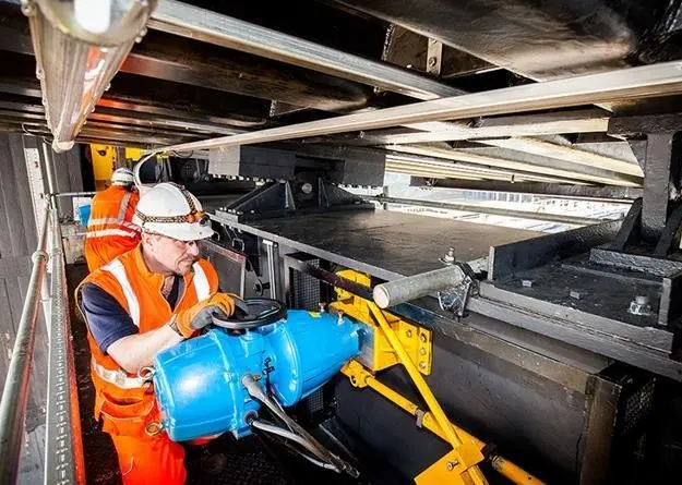
New electric drive motor units are fitted to bespoke carrier assemblies. These link the motors, via a four stage planetary gearbox and coupling, to the new, stronger counterbalance shafts. The assemblies are fixed to the longitudinal floor beams of the upper machinery room, which required the installation of additional steelwork to support the carrier assemblies.
The motor and gearbox units were carefully selected to match the torque requirements of the system.
“We conducted a failure mode and effects analysis workshop. This determined both the static and the dynamic shock loads that the system, in its revised configuration, would need to be designed to accept.” said James Chappell.
AMCO’s solution utilises bespoke Siemens hoisting equipment. This includes the four stage planetary gearbox, which incorporates state of the art technology originally developed for use in wind-turbines. This innovative application allows the linkspans to ‘float’ to take account of the movement of the ferry during unloading and loading, as the gearbox is capable of dealing with the reflected inertia developed when being back driven by the motion of the linkspan resting on the on the vessel.
ELECTRICAL AND CONTROL SYSTEMS
An additional element of the project was to replace and upgrade the electrical and control systems to meet the current regulatory requirements. The new PLC based SCADA (supervisory control and data acquisition) system determines the linkspans’ position, speed and side-to-side vertical alignment using gearbox-driven rotary encoders with new Motor Control Consoles incorporating variable speed drives for the new lifting systems.
The communications between the PLC equipment and field instruments are based on an “open protocol” using a dedicated fibre-optic communications infrastructure.
“A key feature is the ability to monitor the entire system remotely, which will enable prompt and accurate fault diagnostics and improved service resilience” said Mark Willbourn.
The linkspans are operated from a console located within the respective tower control room (bubble), which is positioned to provide direct views of the approaching ferries.
The control system has also been enhanced with a ‘tide-following’ capability, which reduces energy consumption by controlling the range of movement of the linkspans to suit the tidal conditions. Additional safety protocols ensure that the system remains safe should the ferry leave the berth prematurely during loading operations.
According to a project spokesperson, completion of this project is a key milestone in TfL’s investment and life extension programmes ensuring that a safe and reliable service can continue to operate into the 2020s.
By Jake Frith